Secret Comprehensive Mobile Power Internal Circuit Protection Design
Today, the power consumption of smart phones is growing, most of the smart phone battery is not removable, a large-capacity portable mobile power people to travel has become essential electronic products. But recently moved out of the power of frequent accidents, so that consumers and engineers to rethink the design and development of mobile power, and for the internal structure of the mobile power, you have to know how much?
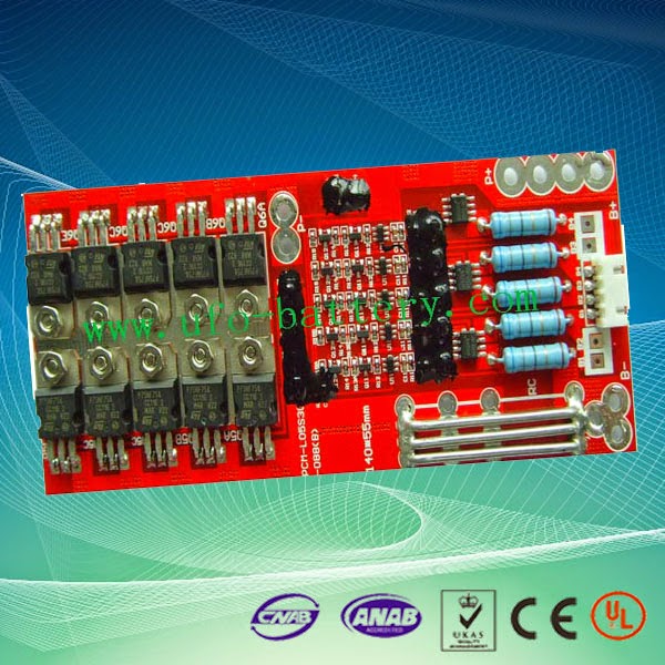 Now smartphone power consumption is growing, most of the smart phone battery is not removable, a large capacity portable mobile power people to travel has become essential electronic products. But recently moved out of the power of frequent accidents, so that consumers and engineers to rethink the design and development of mobile power, and for the internal structure of the mobile power, you have to know how much? Usually consists of a mobile power shell, batteries and proctection circuit boards. Shell is mainly product package, and achieve attractive appearance, protection and so on, common for plastic and metal, some plastic products are often applauded also used fire retardant materials. Board is mainly used for voltage and current control, input and output control, and other features. Mobile power batteries are the most costly part of the 18650 and lithium polymer batteries are the two most common. Aside from batteries, mobile power supply circuit board is also very important. For rechargeable batteries, charging specifications have security and safety cut-off voltage discharge cut-off voltage, there is calibrated rated maximum operating current. Mobile power supply design, the first to be safe polymer battery, because the battery cost is relatively high, and in order to secure reliable operation of the system, there must be a charge management system. When you need to charge portable devices, polymer external battery discharge, because the portable device universal input voltage of 5V, so there is a boost 5V system. Whether charging management system or booster systems are required to provide the board, so moving the internal power supply circuit board designed to determine the quality of the product or not smart.
1. Lithium battery overcharge protection overcharge protection is to detect voltage power management chip implementation, chip set at the reference state (cell phone lithium battery typically 3.5V). When the benchmark rises slowly when rising to VSS-VDD design value, the voltage at this time is to protect overcharge off voltage, by logic low or high output to control external control circuit to achieve overcharge protection. Set VSS-VDD voltage value when the voltage slowly drop to a reference value when the reference is detected at the time of setting the following, which is the logical relationship lift overcharge protection.
2. Over-discharge protection over-discharge protection voltage is the protection of the battery discharge transition lowest voltage to the voltage at the point when the discharge protection circuit cut off the circuit, to protect the battery purposes. Battery life based on the relationship with the depth of discharge and battery voltage and discharge rate and depth of discharge relationship, combined with the actual load equipment to determine the battery discharge voltage, battery discharge protection circuit design.
3. Short circuit protection Short circuit current is generally caused by more than 10 times the rated current, and over-current protection requires a delay of about tens of milliseconds, the number of times the rated current is directly caused by a short circuit within tens of milliseconds, the battery pack will also performance impact. Existing methods are PPTC protection, the method is the heat generated by the current cut off the circuit, also requires millisecond response time, while increasing the loop impedance. There is also dedicated to short-circuit the battery pack integrated chip, this chip narrow range of applications, the high cost.

4.PTC introduce PTC positive temperature coefficient thermistor, also known polyswitch, polymer resettable fuse (polymer resettable fuse) polymer resettable fuse from the polymer matrix and to make it conductive carbon black particles. Since the polymer resettable fuse for the conductor, on which there will be current. When there have been heat (as I2R) current through the polymer resettable fuse, the resulting expansion will make it. So as to separate the carbon black particles, polymer resettable fuse resistance will rise. This will lead to faster polymer resettable fuse produce thermal expansion larger, further increases the resistance. When the temperature reaches 125 ° C, the resistance varies significantly, so that the current significantly reduced. At this flowing polymer resettable fuse small current is sufficient to keep it at this temperature and in a high impedance state. When the fault is cleared, the polymer resettable fuse shrink to its original shape again link up the carbon black particles, thereby reducing the resistance to keep current with specified this level. Understanding of mobile power inside the main components, how do we choose a high-quality mobile power it?
1. Lithium battery overcharge protection overcharge protection is to detect voltage power management chip implementation, chip set at the reference state (cell phone lithium battery typically 3.5V). When the benchmark rises slowly when rising to VSS-VDD design value, the voltage at this time is to protect overcharge off voltage, by logic low or high output to control external control circuit to achieve overcharge protection. Set VSS-VDD voltage value when the voltage slowly drop to a reference value when the reference is detected at the time of setting the following, which is the logical relationship lift overcharge protection.
2. Over-discharge protection over-discharge protection voltage is the protection of the battery discharge transition lowest voltage to the voltage at the point when the discharge protection circuit cut off the circuit, to protect the battery purposes. Battery life based on the relationship with the depth of discharge and battery voltage and discharge rate and depth of discharge relationship, combined with the actual load equipment to determine the battery discharge voltage, battery discharge protection circuit design.
3. Short circuit protection Short circuit current is generally caused by more than 10 times the rated current, and over-current protection requires a delay of about tens of milliseconds, the number of times the rated current is directly caused by a short circuit within tens of milliseconds, the battery pack will also performance impact. Existing methods are PPTC protection, the method is the heat generated by the current cut off the circuit, also requires millisecond response time, while increasing the loop impedance. There is also dedicated to short-circuit the battery pack integrated chip, this chip narrow range of applications, the high cost.
4.PTC introduce PTC positive temperature coefficient thermistor, also known polyswitch, polymer resettable fuse (polymer resettable fuse) polymer resettable fuse from the polymer matrix and to make it conductive carbon black particles. Since the polymer resettable fuse for the conductor, on which there will be current. When there have been heat (as I2R) current through the polymer resettable fuse, the resulting expansion will make it. So as to separate the carbon black particles, polymer resettable fuse resistance will rise. This will lead to faster polymer resettable fuse produce thermal expansion larger, further increases the resistance. When the temperature reaches 125 ° C, the resistance varies significantly, so that the current significantly reduced. At this flowing polymer resettable fuse small current is sufficient to keep it at this temperature and in a high impedance state. When the fault is cleared, the polymer resettable fuse shrink to its original shape again link up the carbon black particles, thereby reducing the resistance to keep current with specified this level. Understanding of mobile power inside the main components, how do we choose a high-quality mobile power it?


Comments
Post a Comment